After completing a 3D scan, the raw data must still be processed before use in modeling, analysis, or 3D printing. Raw point clouds often contain noise, holes, irregular topology, and overlapping surfaces, making post-processing essential in 3D scanning. This guide covers key steps using the MIRACO scanner’s software: automatic editing, manual cleanup, point cloud fusion, mesh generation, and texture mapping, illustrated by scanning a gear on a turntable.
Preparing for Post-Processing
Before diving into post-processing, ensure your object has been properly scanned. For instance, when scanning a gear:
1. Place the gear on a turntable.
2. Select "Standard Mode" with "General" object type.
3. Adjust exposure levels appropriately, especially if the surface is reflective.


Note: While MIRACO’s projector can somewhat capture details from reflective or dark surfaces, it is still recommended to apply scanning spray on these surfaces beforehand to improve capture results.
If the turntable's surface introduces noise in your scan, activate the “Base Removal” feature to eliminate unnecessary background data during scanning.
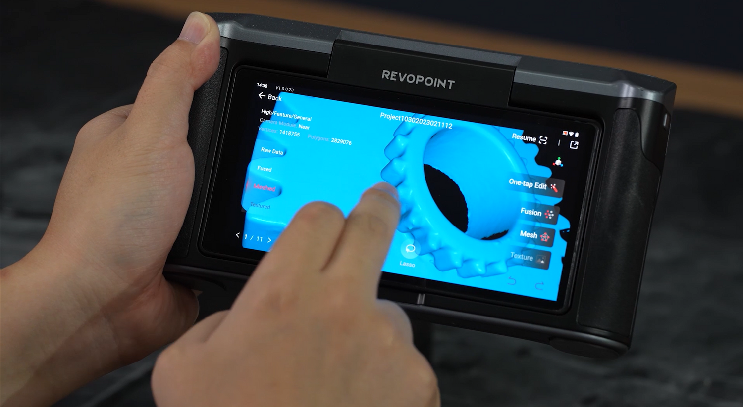
Initial Automatic Processing: Using One-Tap Editing
Once your scan is complete:
1. Navigate to the “Model” section to view your list of scans.
2. Select your desired model and tap on “One-Tap Editing”.


This function automates post-processing tasks: noise reduction, point cloud fusion, and simplification to generate an optimized 3D model. While effective at removing scattered noise, it may not eliminate parts connected to the scanned item, necessitating further manual refinement.
Manual Cleanup: Removing Unwanted Elements
Selecting and Deleting Irrelevant Areas
MIRACO’s software provides two primary selection tools for manual cleanup:
● Lasso Tool: Allows freehand drawing around areas you wish to select.

● Rectangle Tool: Lets you draw rectangular zones to select specific regions.
Use these tools to isolate and delete residual elements attached to your object. However, if unwanted elements closely connect to your main object (e.g., where the gear rests on the turntable), separating them cleanly may be difficult.
Improving Object Support for Better Separation

To facilitate better separation between your object and its base during scanning:
● Try placing a small cup or platform between the gear and the turntable.
● This elevates the gear slightly and creates visible separation in the scan data.
● It also allows better capture of bottom-edge details and simplifies later editing.
When rescanning with this modified setup:
● Continue using “Standard Mode”.
● Adjust exposure levels as needed.
● Adjust the scanning angles strategically to ensure that all sides and edges of the gear are thoroughly covered.
This approach yields cleaner data and minimizes reliance on manual cleanup.
Advanced Manual Editing Workflow
Once you've removed obvious unwanted elements, enter the post-processing interface by selecting your model again. Here you can apply more refined editing tools.
Fusion (Point Cloud Merging)
This step combines multiple raw point clouds into one single point cloud. There are two fusion methods available.

Standard Fusion
● Enables minimum point spacing as low as 0.05 mm.
● Retains high levels of detail.
● Requires more processing time due to point density.
Advanced Fusion
● Minimum point spacing is 0.1 mm.
● Automatically smooths denser areas based on point cloud distribution.
● Produces more balanced results with improved surface consistency.
Tip: Smaller point spacing increases model density and quality but significantly raises processing time. A moderate setting, such as 0.3 mm, often strikes a balance between quality and efficiency.
Isolation (Removing Disconnected Elements)
This tool automatically detects and removes disconnected parts of your scan, like support structures or stray noise.
Adjust an "Isolation Ratio" parameter to determine how much gets detected.
● Lower ratios detect only small fragments.

● Higher ratios detect larger attached components as isolated objects, too.

Note: An appropriate isolation ratio deletes only true extraneous elements, preserving all parts of your main object.
Overlap Detection (Eliminating Redundant Data)
During scanning, covering multiple angles may result in the same area being captured multiple times, causing overlapping points that lead to thickness inconsistencies or rough textures.

The Overlap Detection tool efficiently identifies and removes overlapped data clusters.
Tip: Default settings usually work well in most cases. No extensive adjustment should be needed unless dealing with complex geometries.
Surface Smoothing

Apply smoothing to enhance visuals and reduce surface irregularities.
Caution: Excessive smoothing can erase fine details crucial for accurate modeling, particularly on textured surfaces such as gears and intricate mechanical components. Use this feature sparingly on detailed objects, but apply stronger smoothing on flat or simple surfaces where detail loss is less concerning.
Generating Mesh Models from Point Clouds
When you are satisfied with your point cloud after fusion and cleanup, convert it into a polygonal mesh for use in CAD or animation software.
Mesh Quality
Higher values create refined meshes with more triangles but also increase processing time and file size. Choose based on your use case.

● High quality for 3D modeling.
● Medium quality for general visualization.
● Low quality for quick previews or low-resource environments.
Hole Filling (Auto Fill Gaps)
During mesh generation, some areas may have missing data from occlusions or limited visibility (e.g., deep grooves).
The hole-filling feature seeks to automatically close these gaps by analyzing surrounding geometric patterns.
Set a fill ratio to define the size of a hole for filling.
● A 30% setting fills holes smaller than one-third of the total model size.
Warning: Using a high fill ratio might cause intentional openings, such as holes in gears, to be mistakenly filled as defects. To avoid this, set the fill ratio lower (e.g., 3%) so only minor imperfections are patched while structural features remain untouched.

Additional Mesh Tools
After generating your mesh model, you may want to refine it using these optional tools.
Isolation Check (Again)
Even after cleanup, tiny fragments might persist in mesh form if missed due to changing size thresholds during point cloud conversion. Rerunning isolation ensures nothing is left behind.
Simplify Mesh
This reduces triangle count by merging adjacent faces without altering the overall shape, making it ideal for reducing file size before exporting or sharing models online.
Note: Avoid oversimplifying! Reducing too much can distort important features like sharp edges or holes, vital for engineering applications.
Mesh Smoothing
Similar to earlier surface smoothing, this process applies at the mesh level instead of the point cloud stage. It helps eliminate jagged transitions between triangles caused by uneven triangulation during meshing.
Repeat until desired smoothness is achieved, but visually check that key features remain intact.
Applying Texture Mapping (For Color Scans Only)
If you performed color scans using MIRACO’s RGB camera. Tap “Texture” after completing mesh generation.

The system maps color information onto mesh surfaces using UV techniques, resulting in realistic colored models for presentation or archiving.

Note: If you've used “One-Tap Editing”, texture mapping is included and only needs reapplying if changes occur afterward.

Tutorial Video
Leave a comment
This site is protected by hCaptcha and the hCaptcha Privacy Policy and Terms of Service apply.