


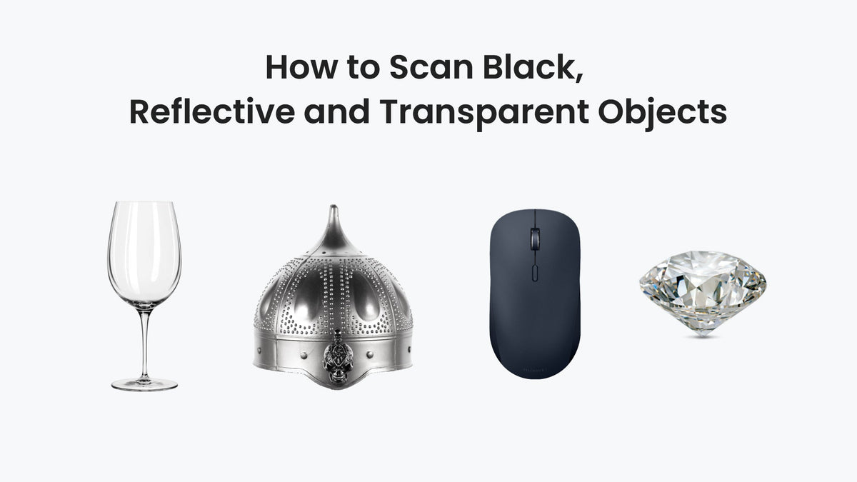
Scanning black, reflective, and transparent objects is possible, but these surfaces can make a normal scan less stable. The issue is not simply whether a 3D scanner is powerful enough. Dark materials may return too little light, reflective surfaces can redirect the projected pattern, and transparent materials can transmit or distort it. The best results come from matching the scanner mode, surface preparation, lighting, tracking, and processing workflow to the object. This guide explains practical steps for preparing each surface and checking the scan before using it for 3D printing, CAD, inspection, or reverse engineering.
Why black, reflective and transparent surfaces challenge a 3D scanner
A 3D scanner needs consistent visual information to determine the position of points on an object's surface. A very dark surface can return a weak signal, while a mirror-like surface may send projected light away from the scanner or create bright highlights. A clear object can allow light to pass through or show the background behind it. These effects can lead to missing points, unstable tracking, noisy edges, or a mesh that represents the surrounding environment instead of the object.

Surface colour is only one part of the problem. Gloss, transparency, texture, object size, ambient light, and the amount of visible geometry all affect the capture. A matte black component with clear edges may be easier to scan than a glossy white component with few features. Treat the surface and the geometry as one scanning problem rather than relying on a single specification or automatic setting.
Before scanning, prepare the object, environment and workflow
Start with a clean, stable object. Remove dust, fingerprints, loose labels, and anything that can move during capture. Fix the object or place it on a stable turntable if the workflow allows. If the object has removable parts, decide whether they should be scanned together or separately before starting. A short test scan on a representative area can reveal whether the surface needs treatment before you spend time capturing the complete object.
Control the surrounding environment as well. Keep lighting consistent, avoid strong reflections from windows or lamps, and use a background that does not resemble the object. Keep the scanner at the recommended working distance and move at a steady pace. Select a capture mode according to the material, object size, detail, and required output rather than assuming the fastest mode will produce the most complete data. If you change the light, distance, exposure, or surface treatment halfway through a scan, alignment and texture quality may become less consistent.
|
Surface |
Challenge |
First response |
Scan focus |
Avoid |
|---|---|---|---|---|
|
Black |
Low light |
Matte if allowed |
Steady distance |
Dark background |
|
Reflective |
Glare |
Diffuse light |
Change angle |
Direct light |
|
Transparent |
Light passes |
Opaque coat |
Visible surfaces |
Background showing through |
How to scan black objects with a 3D scanner
Black surfaces can absorb much of the projected light, leaving the scanner with less information to read. Begin with the capture mode and exposure guidance supplied for your 3D scanner. Keep the scanner close enough to maintain a strong signal, but not so close that parts of the projected pattern fall outside the capture area. Move slowly and keep the target surface within view instead of making long, fast passes.
Matte black is often easier to capture than glossy black because it produces less glare. If the material and project allow it, a removable scanning spray or another approved matte coating can make the surface more uniform. Test the coating on a hidden area first, check whether it can be removed safely, and follow the manufacturer's handling instructions. Do not coat an object when the coating could damage it, alter a critical dimension, or create a safety or compliance issue.
Tracking is also important. When the black surface has few visible features, add reference markers only where they are permitted and will not affect the final use of the object. Capture overlapping views of edges, holes, and transitions so the software has geometry to connect. If the scan begins to lose tracking, stop, return to a clearly captured area, and continue with shorter passes rather than forcing the scanner forward.
How to scan reflective objects with a 3D scanner
Reflective objects can produce unstable points because the scanner sees changing highlights instead of a consistent surface. Polished metal, glossy plastic, coated panels, and glass-like finishes are especially sensitive to the angle of the scanner and the position of nearby light sources. Wipe the object clean, remove fingerprints, and arrange the workspace so direct light does not bounce into the scanner.
A removable scanning spray or suitable matte treatment can diffuse reflections and create a more even capture surface. The right choice depends on the material, the required dimensional tolerance, and whether the object can be cleaned afterwards. For a production or inspection workflow, record the treatment used and confirm that it does not build up on edges or change the dimensions being measured.
If coating is not possible, adjust the scan path instead. Try a different viewing angle, reduce direct lighting, and capture the object in smaller sections with generous overlap. Keep the scanner and object moving smoothly so the surface does not alternate rapidly between glare and shadow. Some reflective objects may still produce incomplete data without surface preparation, so validate a sample area before committing to a full scan.
How to scan transparent objects with a 3D scanner
Transparent objects are difficult because projected light can pass through them, reflect from several layers, or reveal the background. The scanner may capture an inner wall, a rear surface, or nearby objects instead of the outer boundary you need. Clear acrylic, glass, transparent resin, and glossy translucent plastics can therefore require more preparation than an opaque object with the same shape.
If the object can be treated safely, apply a removable opaque coating designed for 3D scanning. A temporary matte surface gives the scanner a clearer boundary to capture. Confirm that the coating is compatible with the material, does not enter openings, and can be removed without leaving residue. For high-value or delicate objects, test the complete process on a sample before scanning the original.
Capture the object from several angles and inspect the result for double surfaces, background points, and missing edges. If an internal feature is important, plan a separate capture rather than assuming a clear exterior scan will reveal it automatically. For critical work, document which surfaces were visible, which were coated, and which areas still need manual modelling or an alternative measurement method.
Revopoint model recommendations for difficult surfaces
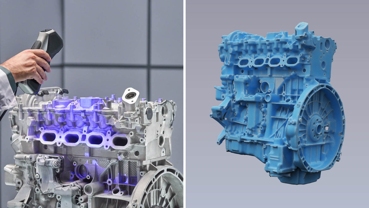
Revopoint POP 4 is a flexible handheld option that supports a range of scanning needs for small-to-medium objects through its handheld and desktop workflows. Its marker support and compatibility with Revo Scan 6 help users build a repeatable workflow for 3D printing and modelling. Its blue multi-line laser mode can capture dark or highly reflective surfaces without scanning spray in suitable conditions. For transparent objects, or when a more uniform surface is needed, use a compatible removable scanning spray and test it on a representative area before capturing the full object.

For a more demanding small-to-medium-object workflow, Revopoint MetroX Pro is the advanced choice. Its multi-line blue laser and full-field blue structured-light modes are designed for detailed capture, while its laser modes can scan black or shiny surfaces without spray in suitable conditions. Transparent or specular surfaces still require scanning spray, and the result should be validated against the tolerance required for inspection, CAD, or reverse engineering.

For low-feature or difficult surfaces, reference markers can support alignment when the object and project allow them. Place markers where they will not cover important geometry, and use enough visible reference to connect adjacent views. Compare each Revopoint scanner's supported modes, working distance, object-size range, tracking method, software workflow, and surface-preparation requirements against the actual project. The best fit is the scanner that produces usable data through a repeatable process, not necessarily the model with the highest number on one specification.
Keep tracking stable across difficult surfaces
Tracking can fail when the scanner cannot find enough repeatable features between frames. Black, reflective, and transparent surfaces can make this worse, especially when the object is rotated quickly or the scanner moves outside its recommended distance. Start and finish each pass on an area that has already been captured, and keep enough overlap for the software to recognise the next section.
Plan the scan around occluded areas. Rotate the object to expose hidden edges, change the angle gradually, and return to the same reference points after each rotation. If a part contains a deep cavity, capture the cavity separately and check that the opening is aligned with the surrounding surface. It is better to create several controlled passes than one long pass with uncertain alignment.
If tracking drifts, pause and review the last stable frame. Delete or isolate the failed section before continuing, then restart from a reliable overlap area. Continuing through a drift can spread the error across the whole mesh and make it harder to tell which part of the result is trustworthy.
Post-process and validate the scan
After capture, inspect the raw point cloud or individual scan frames before smoothing or filling holes. Remove obvious stray points, isolate the object from the background, and align separate passes using reliable geometry. On a difficult surface, missing data may look like a shallow depression or a smooth patch, so compare the mesh with the physical object as you work.
Use smoothing and hole filling conservatively. These tools can improve the appearance of a model, but they can also hide a gap, round a sharp edge, or create geometry that was never captured. Keep the original scan data separate from the processed copy, and record which areas were repaired manually. This makes it easier to revisit the workflow when the model will be used for inspection, reverse engineering, or a production decision.
A completed mesh is not automatically an accurate mesh. For 3D printing, check for holes, flipped normals, thin walls, and unwanted background geometry before exporting. For CAD or reverse engineering, compare key dimensions with a trusted reference measurement. For inspection, define the measurement method and tolerance before deciding whether the scan is acceptable.
Before choosing a 3D scanner, review these practical points:
· the colour, gloss, transparency, texture, and cleanliness of the objects you will scan
· the typical object size, smallest detail, deep cavities, and areas that must remain dimensionally reliable
· the available capture modes, working distance, tracking method, and whether markers or coating are allowed
· the lighting, background, turntable, mounting, and workspace conditions you can keep consistent
· the software, export formats, processing tools, and validation method required after capture
A sample scan with the actual material is one of the most useful checks before choosing a 3D scanner. Test the complete path from preparation and capture to alignment, export, and final use. This reveals problems that a product specification alone may not show and helps the team set realistic expectations for black, reflective, and transparent objects.
Conclusion
A black, reflective, or transparent object does not automatically rule out 3D scanning, but it does require a more deliberate workflow. Prepare the surface when appropriate, control the lighting, keep tracking stable, capture enough overlapping views, and validate the final geometry before using it. Revopoint POP 4 can be a flexible handheld choice for varied scanning workflows, including dark or shiny surfaces through its laser mode without scanning spray in suitable conditions, while transparent surfaces may benefit from a compatible removable scanning spray. Meanwhile, MetroX Pro is better suited to demanding small-to-medium workpieces and black or shiny surfaces. Transparent and specular surfaces still require careful preparation and validation. With the right preparation and Revopoint model, scanning can support 3D printing, inspection, CAD, and reverse engineering.


Leave a comment
This site is protected by hCaptcha and the hCaptcha Privacy Policy and Terms of Service apply.