


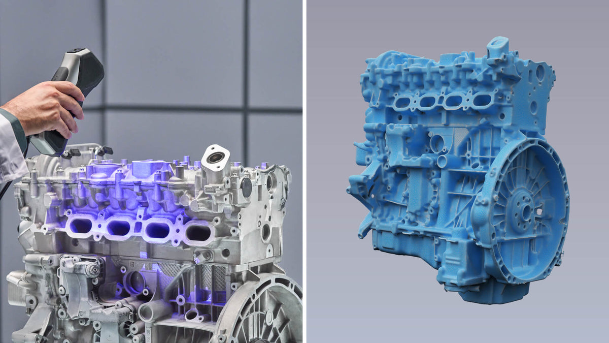
Factory equipment is rarely identical to the drawings that describe it. Machines are modified, guards are replaced, components are moved, and repairs can introduce changes that never make it back into the original CAD files. For maintenance teams, this creates a familiar problem: the asset in front of them is often more accurate than the documentation they are expected to use.
A digital twin built from 3D scan data provides a current geometric reference for the equipment as it exists today. It can help teams understand access points, record as-built conditions, plan replacement parts, review clearance, and communicate maintenance work without relying on incomplete drawings or memory alone.
What a digital twin means for factory equipment
A digital twin is more than a 3D model that looks like a machine. For maintenance purposes, it is a digital representation of a physical asset that can be connected to useful information such as an asset number, location, service history, inspection notes, photographs, measurements, manuals, and replacement-part records.
The geometry is the foundation. It shows the shape, interfaces, mounting points, access panels, pipe or cable routes, and surrounding clearances that technicians need to understand before work begins. The wider twin becomes more useful when that geometry is linked to the operational information already held by the factory.
The objective is not to create a perfect visual copy of every object in the plant. The objective is to capture the parts of the equipment that support a real decision: how to remove a cover, whether a replacement will fit, where a service tool can be positioned, or how a modified assembly differs from its original condition.
Why 3D scanning is useful when factory equipment changes
Factories change continuously. A production line may be expanded, a machine may be adapted for a new process, and a discontinued component may be replaced with a locally designed part. Even small changes can make an old drawing unreliable when the maintenance task depends on exact geometry.
3D scanning records the physical condition directly. Instead of beginning with a blank CAD file, a technician or engineer can capture the equipment, process the scan, and use the resulting geometry as a reference for documentation, design, inspection, or reverse engineering.
This is especially useful for legacy equipment. Original files may be missing, stored in an obsolete format, or different from the machine after years of repairs. A scan can preserve the current condition before the next modification, helping the factory build a more dependable record over time.
Revopoint scanner recommendations for factory digital twins
For a factory digital-twin workflow, three Revopoint options are particularly relevant because they cover different asset sizes and working environments.
|
Factory need |
Recommended device |
Capture context |
Digital-twin use |
Planning note |
|---|---|---|---|---|
|
Detailed components |
MetroY Ultra |
Small or medium parts |
CAD reference and replacement parts |
Validate critical interfaces |
|
Large installed equipment |
Trackit SR |
Assemblies and machine frames |
As-built layout and clearance |
Plan tracking and occluded areas |
|
Mobile plant-floor survey |
MIRACO Plus |
Equipment that cannot be moved |
Fast documentation and first-pass review |
Return with a specialist setup if needed |
Revopoint MetroY Ultra for detailed components and maintenance-critical parts
MetroY Ultra is a strong fit for small to medium workpieces where fine geometry, edges, holes, and surface detail need to be captured clearly. Its multi-line blue laser and full-field structured-light modes support up to 0.01 mm single-frame precision, up to 0.015 mm single-frame accuracy, and a volumetric accuracy of 0.015 mm + 0.04 mm × L (m). With a working distance of 200–400 mm, it gives teams flexibility when a component contains a mixture of flat faces, curved surfaces, recessed features, or difficult industrial finishes.

It can capture up to 3,000,000 points per second in multi-line laser mode and up to 7,000,000 points per second in full-field structured-light mode, with scanning speeds of up to 90 fps and a fused point distance of up to 0.05 mm. This makes it suitable for maintenance-critical components, machine guards, brackets, tooling, housings, and parts that may need to be measured or rebuilt. The scan can be processed into engineering data for CAD reconstruction, inspection, or a replacement-part workflow rather than being used only as a visual reference.
Revopoint Trackit SR for larger equipment and assemblies
Trackit SR is better suited to larger industrial equipment, assemblies, and workpieces that are difficult to place on a small scanning table. Its optical tracking approach supports up to 0.02 mm single-frame accuracy and a tracking-system volumetric accuracy of 0.025 mm + 0.04 mm × L (m). The scanner has a working distance of 200–500 mm, while the tracker operates from 800–2,500 mm and provides a tracking volume of up to 3 m³.

For digital-twin projects, this can simplify the capture of large machine frames, production-line components, fixtures, and equipment that needs to be documented in its installed condition. Trackit SR uses 30 blue cross-line lasers for detailed areas, 17 blue parallel lines for larger low-feature surfaces, and a single blue line for deep holes. It supports recommended workpiece sizes from 0.01 to 4 m, scanning speeds of up to 2,000,000 points per second, Wi-Fi 6 wireless scanning, and up to 2.5 hours of battery life. A marker-free workflow can also reduce preparation time when the surface must remain untouched, although the tracking setup and site conditions still need to be planned carefully.
Revopoint MIRACO Plus for mobile, plant-floor documentation
MIRACO Plus is useful when the team needs to scan directly on the factory floor and process data without depending on a permanently tethered computer. Its standalone workflow supports up to 0.04 mm single-frame accuracy, photogrammetric length accuracy of 0.02 mm + 0.05 mm × L (m), and scanning speeds of up to 20 fps. With a 100–1,000 mm working distance, it can capture objects from a minimum scan volume of 10 × 10 × 10 mm up to a maximum scan volume of 4 × 4 × 4 m.

The scanner combines quad-camera infrared structured light, a 48 MP RGB camera, an 8-core 2.4 GHz processor, 256 GB of storage, and a 5,000 mAh battery that supports up to two hours of continuous scanning. Its standalone workflow makes it practical for equipment that is difficult to move, remote service areas, maintenance rooms, and early-stage surveys where the team needs to assess the asset before deciding how much detail is required.
It can also support a flexible approach to asset capture. A team may use it to document the overall equipment first, then return with a more specialised scanner when a particular component requires closer measurement or scan-to-CAD work.
These devices do not have to be treated as competing choices. A factory may use Trackit SR for the overall assembly, MIRACO Plus for mobile documentation, and MetroY Ultra for a small component that needs more detailed engineering data.
A practical factory digital-twin workflow
1. Define the asset boundary and purpose
Start by deciding what belongs in the twin. It may be one replacement part, a complete machine, a production cell, or the space around a piece of equipment. Record the asset number, capture date, responsible team, and the maintenance question the scan is intended to answer.
2. Prepare the equipment and capture reliable geometry
Clean loose dirt, dust, grease, labels, and temporary objects that could move during scanning. Stabilise doors, covers, hoses, and other parts that should remain in a known position. Control lighting where possible, reduce unnecessary reflections, and make sure the scanner can reach the important surfaces from several angles.
Dark, glossy, metallic, or transparent surfaces may require a different scanning mode, a temporary surface treatment, or a more deliberate scan path. Low-feature surfaces may need suitable reference information for tracking. The correct preparation depends on the asset and on whether the final twin is intended for measurement, documentation, or design.
3. Process the scan into usable engineering data
After capture, review the raw scans before smoothing or filling holes. Remove stray points, isolate the equipment from the background, align separate passes, and generate a mesh only after the coverage is reliable. Revo Scan, Revo Metro, or the software workflow matched to the selected scanner can support the processing stage.
Do not allow post-processing to create geometry that was never captured. Excessive smoothing can round a sharp edge, while automatic hole filling can hide an opening or invent a surface. Keep the original scan data so the team can return to it if a later design or maintenance question requires additional evidence.
4. Connect geometry to the asset record
A digital twin becomes more useful when the model is stored with the information people need to find it again. Use a consistent asset ID and file naming system. Record the scanner, capture mode, software version, capture date, coordinate system, important tolerances, and any areas that were inaccessible.
The processed model can then be linked to maintenance software, a document-management system, CAD files, inspection reports, photographs, and service instructions. The exact platform will vary by factory, but the principle is the same: the scan should be part of the asset record rather than an isolated file on one technician's computer.
5. Validate before making a maintenance decision
A scan is evidence, not an automatic engineering approval. Check critical dimensions against a trusted reference, drawing, gauge, or measurement method. If the model will be used to fabricate a replacement part, confirm the interfaces and tolerances that affect fit and function. If it will be used for access planning, verify the relevant clearances at the physical equipment.
Where digital twins improve maintenance work
As-built equipment records
A scan can document the condition of a machine after installation, relocation, or modification. This creates a current reference for future technicians and can reduce the time spent trying to reconstruct what changed during a previous project.
Replacement parts and reverse engineering
When a component is discontinued or its CAD file is missing, scan data can provide the geometric starting point for reconstruction. MetroY Ultra is appropriate for smaller, detail-heavy parts, while larger equipment can be captured with a tracking or mobile workflow before the relevant component is modelled in CAD.
The scan does not replace engineering judgement or material analysis. It reduces the amount of geometry that must be guessed or rebuilt manually, allowing the team to focus on fit, function, material choice, and manufacturing requirements.
Access, clearance, and work instructions
Maintenance work often fails because the team cannot see the complete access problem before arriving at the machine. A current 3D record can help review whether a cover can be removed, whether a tool has enough clearance, or whether a temporary support will interfere with nearby equipment.
The same model can support clearer work instructions. Instead of relying only on photographs from one angle, the team can refer to a digital view of the relevant assembly and identify the areas that need to be isolated, removed, or protected.
Conclusion
3D scanning gives factories a practical way to build digital twins from the equipment that actually exists on the plant floor. The value is not limited to a detailed 3D model. A well-captured and well-managed twin can support as-built documentation, maintenance access planning, replacement-part development, change detection, training, and safer communication between engineering and operations.
For detailed small and medium components, Revopoint MetroY Ultra provides a strong starting point. For larger installed equipment and assemblies, Revopoint Trackit SR is better suited to a tracked industrial capture workflow. For mobile documentation and standalone processing, MIRACO Plus adds flexibility on the plant floor. The right choice depends on the asset, the maintenance question, and the level of validation required.
When scan data is connected to asset records and kept current after maintenance work, it becomes more than a one-time capture. It becomes a reusable digital reference that helps factory teams make better decisions throughout the equipment lifecycle.

Leave a comment
This site is protected by hCaptcha and the hCaptcha Privacy Policy and Terms of Service apply.