


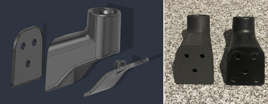
For classic car enthusiasts, the hardest parts to replace are often small components that have been out of production for decades. Tiago Cardoso faced this challenge with the original mirror base used on later UMM Alter vehicles—particularly the “93” or “Milésimo” version with chassis numbers above 45,000.
His goal was to preserve the discontinued part’s geometry and mounting points in a digital model, then create a replacement he could test on the vehicle.
When Measuring a Rare Part Isn't Enough
Before adopting 3D scanning, Tiago's reverse-engineering work relied mainly on calipers, rulers, gauges, photographs, and manual CAD reconstruction.
That approach works reasonably well for simple mechanical components. But the mirror base presented a different challenge.
The biggest problem was not measuring one dimension accurately. It was capturing the complete geometry and maintaining the relationship between its different curves, surfaces, and mounting features.
Repeatedly returning to the physical part for additional measurements also made the CAD process time-consuming.
“Some of the shapes and curved surfaces would be extremely difficult, if not impossible, to accurately reproduce using only dimensions and calipers.”
Instead of reconstructing the part from a collection of measurements, Tiago could capture the original geometry as a complete 3D reference and keep returning to that digital data throughout the design process.
That became the foundation of the project.
Capturing Complex Geometry with MetroY
Tiago chose the Revopoint MetroY for the mirror base, describing it as an industrial-grade scanner with a strong balance of accuracy, portability, ease of use, and price-to-performance ratio.

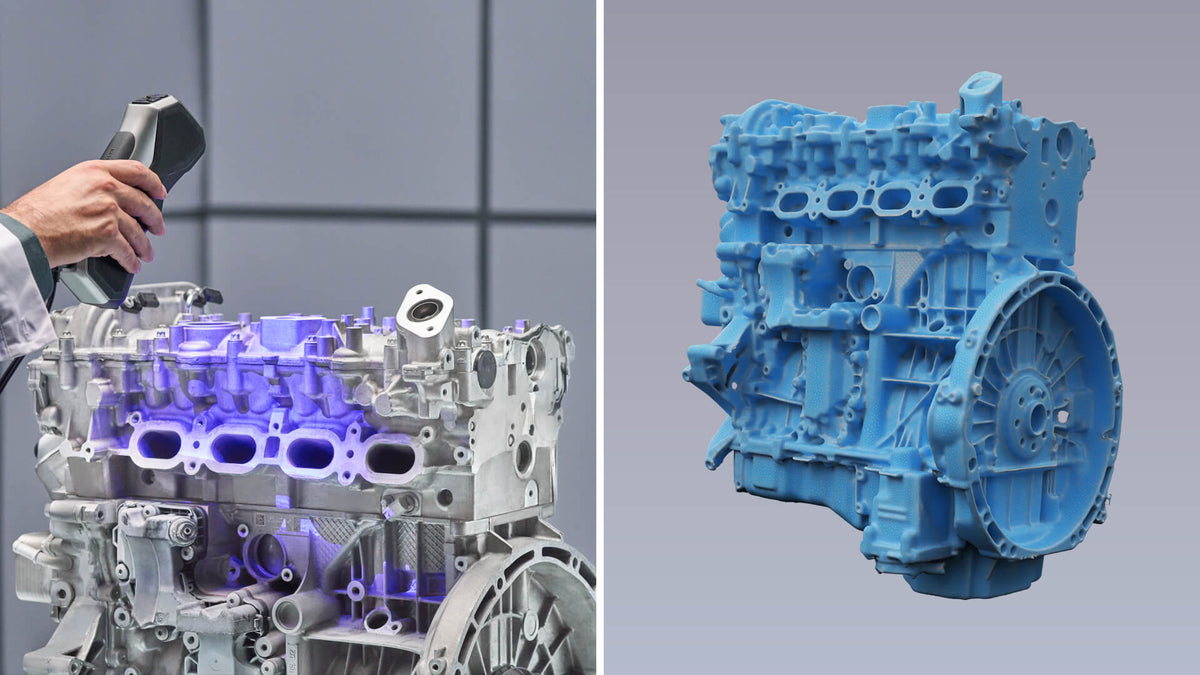
The MetroY is built around blue laser scanning with three dedicated modes: cross-line, parallel-line, and single-line scanning. This allows users to switch between fast coverage, detailed surface capture, and modes for difficult features such as deep holes and narrow areas. It can capture flat, shiny, or black surfaces without scanning spray, while its cross-line mode reaches up to 1.5 million points per second.
For reverse engineering, this flexibility matters because a single component can contain very different types of geometry.
Tiago's experience also provided an interesting real-world comparison. A friend using another brand's scanner was unable to capture some areas of the mirror base in sufficient detail. He eventually asked Tiago to scan the part with the MetroY.
For Tiago, that detailed capture was essential—not because the goal was simply to create a visually recognizable model, but because the scan needed to serve as a reliable reference for rebuilding the actual part.
Planning a reverse-engineering project of your own? Use code REVONEWS26 at checkout to get an additional 2–5% off the MetroY.
From Raw Scans to a Usable Digital Reference
The scanning process was only the first step.
Tiago placed the mirror base on a self-made scanning table, slightly larger than the standard table included in the kit. After capturing the scans, he processed them in Revo Metro, then moved the data into Revo Design.

Revo Metro provides a complete workflow for processing MetroY scan data, including real-time point-cloud monitoring, fusion and meshing tools, cleanup, hole filling, smoothing, and model simplification. It also supports common formats such as PLY, OBJ, STL, and 3MF for integration with other CAD, modeling, and manufacturing software.
For Tiago, the important part was having a clean, usable mesh that could serve as the geometric reference for the next stage.
In Revo Design, he aligned the final mesh and created sketches to extract the measurements he needed.
This is where the workflow moved beyond simply “scanning an object.”
The scan became engineering data that could be queried, measured, and used for reconstruction.

From Scan to CAD: Reconstructing the Original Geometry
Once the mesh was aligned, Tiago imported it into Fusion 360 and began rebuilding the mirror base using the scan as a reference.
Whenever he needed an additional dimension, he could return to Revo Design and check the original scan rather than going back to the physical part.

This created a much more flexible reverse-engineering workflow:
Scan → Process → Align → Measure → Reconstruct → Refine
Revo Design is specifically built around this scan-to-CAD workflow, with tools for mesh editing, surface reconstruction, freeform and parametric modeling, cross sections, sketching, scan-to-CAD comparison, and standard CAD export formats such as IGES and STEP.
For a part like the UMM mirror base, this means the scan does not have to become the final CAD model directly. Instead, it provides the geometric truth from which the engineer can reconstruct a clean, manufacturable design.
After several iterations and some trial and error, Tiago produced a matching CAD model.
From Digital Model to a Real Replacement
The project did not stop at the CAD screen.
As a 3D printing enthusiast, Tiago could immediately turn the digital design into a physical prototype. He printed the mirror base using an FDM printer with PA-CF filament and test-fitted it directly onto the vehicle.

The result was a strong validation of the workflow.
The printed part fitted the original mounting points correctly and closely matched the original component. After the initial test fit, Tiago installed the part on the vehicle, where it is now undergoing road testing.
The road test will provide further validation of the part's durability and performance before the design is considered finalized.
That distinction is important.
The objective was not simply to create an accurate-looking digital model. It was to create a functional replacement that could interact correctly with the real vehicle.
50–70% Less Time for Reverse Engineering
The most measurable benefit was efficiency.
Tiago estimates that 3D scanning reduced the time required for this type of work by approximately 50–70% compared with manually measuring and reconstructing the part.
The complete mesh also reduced the need for repeated physical measurements and helped reduce prototype iterations.
The difference can be summarized simply:
Traditional approach
Measure → Reconstruct → Check → Measure Again → Correct → Prototype
3D scanning workflow
Scan → Reference the complete geometry → Reconstruct → Prototype → Test

Instead of repeatedly asking, “What was that dimension again?”, Tiago could return to the same digital representation of the original part whenever another measurement was needed.
The result was not just a faster scan. It was a more efficient reverse-engineering process from physical part to manufacturable design.
Accuracy That Matches the Application
Interestingly, Tiago did not need extreme accuracy for the UMM mirror base itself.
The original mirror had been warped by sunlight and environmental exposure, so reproducing every deformation at an ultra-high level of accuracy would not have been useful for the restoration.
However, Tiago has independently verified the MetroY's accuracy on another machined alloy component.
In that project, he knew from the original CAD specification that the distance from a specific point to a bolt thread was exactly 80 mm. After scanning the part and extracting the measurement in Revo Design, he obtained 80.003 mm.
The example highlights an important point about reverse engineering: accuracy needs to be considered in the context of the application.
The goal is not simply to chase the smallest possible number. It is to capture enough accurate geometric information to make a part that fits, functions, and performs as intended.
MetroY is designed for precisely this type of work, with single-frame accuracy of up to 0.02 mm and scan data suitable for measurement and scan-to-CAD workflows.
Preserving a Part That May Never Be Made Again
For Tiago, the value of the project extends beyond restoring one vehicle.
The original mirror base is no longer produced. By preserving its geometry digitally, he now has what he describes as a kind of “secret recipe.”
If the printed replacement eventually fails because of age or environmental conditions, he can simply produce another one without starting the reverse-engineering process from scratch.
This changes the role of 3D scanning in classic car restoration.
The original component is no longer the only source of truth.
Once scanned, its geometry can become a reusable digital blueprint for future reproduction, redesign, or manufacturing.

Building a Digital Archive of Automotive History
Classic vehicles contain thousands of components that were manufactured in limited quantities and may never be produced again.
As these vehicles age, the original parts become increasingly vulnerable to wear, damage, and loss.
3D scanning offers a way to preserve these components before they disappear.
For restoration enthusiasts and engineers, the workflow can be as straightforward as:
Preserve the Original → Capture the Geometry → Build the CAD Model → Prototype → Test → Reproduce When Needed
Tiago sees this as more than a solution for his own vehicle.
“In the future it will be much easier to reproduce these parts because we will have their 3D ‘blueprints’ digitally preserved, even when the original parts are no longer available.”
His UMM Alter mirror-base project shows how a modern 3D scanning and scan-to-CAD workflow can bridge the gap between a rare physical component and a reproducible digital design.
The original part may eventually disappear through age, wear, or damage.
Its geometry doesn't have to.

Leave a comment
This site is protected by hCaptcha and the hCaptcha Privacy Policy and Terms of Service apply.