Engineers use GD&T every day, but the system itself is rarely discussed in plain terms. This article steps back from individual symbols and explains GD&T as a language, how it defines allowable geometry and structural design intent, and why its framework underpins modern technical drawings.
But what exactly is GD&T, and why is it used everywhere from aerospace to hobbyist workshops?
What Is GD&T?
GD&T stands for Geometric Dimensioning and Tolerancing. At its core, it’s a language of standardized symbols and rules that describe how a part should be manufactured and how it should function. Instead of relying only on basic measurements like “100 mm from this edge” or “30 mm wide,” GD&T clarifies a part’s geometry.
It tells manufacturers not only what size something should be but also how that feature should behave. Should a surface be perfectly flat? Should a hole be centered relative to two other features? Should two rails always stay parallel, regardless of circumstances? GD&T defines these relationships to ensure parts fit together as intended.
Why GD&T Exists
Manufactured parts are never perfectly made. Tools wear out, machines vibrate, materials expand and contract, and no dimension is exactly as printed on the drawing. Without a simple way to define acceptable variation levels, minor inconsistencies can lead to misaligned parts or malfunctioning assemblies.

That’s where GD&T comes into play. It provides a way to describe the “functional intent” of a design. Instead of simply saying “this bracket needs two holes,” GD&T explains how those holes should relate to the rest of the part, how straight they must be, how accurately they should be positioned, and what surfaces they should reference. This greatly reduces confusion and ensures that everyone, from designers to machinists to inspectors, is speaking the same language.
Another benefit of GD&T is that it helps lower costs. Because it helps engineers to balance quality with practicality by applying accuracy only where needed, it avoids overly tight tolerances that increase machining and inspection time.
The Core Ideas Behind GD&T
If you strip away the symbols, GD&T is based on a few key ideas.
First, there are feature control frames, small rectangular boxes that contain a symbol, a tolerance, and sometimes references to other features called datums. These frames tell you exactly how to interpret the requirement, what geometric characteristics the feature must follow, how much variation is allowed, and which other surfaces or features it must relate to.
Next, there are datums, which act as reference points for measuring everything else. A datum could be a flat surface that marks the bottom of a part, a central axis of a hole, or even a plane formed by multiple surfaces. Once the datum is set, all related measurements are referenced to that stable feature to ensure stable inspection.

Finally, there are 14 geometric symbols that represent different types of tolerances. Some control form (like flatness or circularity), other control orientation (such as parallelism or perpendicularity), and some control location (for example, position). Collectively, they cover nearly every geometric requirement a part might have.
How GD&T Works in Manufacturing
To understand the value of GD&T, imagine machining a flat plate that needs a perfectly sealed surface. A simple dimension can’t tell you whether a surface is warped or slightly twisted, but a flatness tolerance can. Or imagine an engine bracket that relies on the exact location of a hole for alignment. A traditional dimension from an imperfect edge won’t guarantee accuracy, but a positional tolerance referenced to establish datums will.

GD&T enhances consistency and safety across industries such as automotive, aerospace, medical devices, robotics, consumer electronics, and more. With the rise of 3D printing and hobbyist CNC machining, GD&T is increasingly important even for small workshops and independent creators.
How GD&T Connects to 3D Scanning
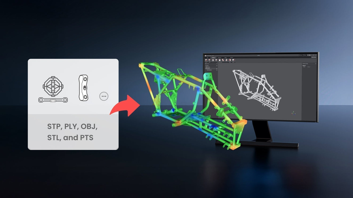
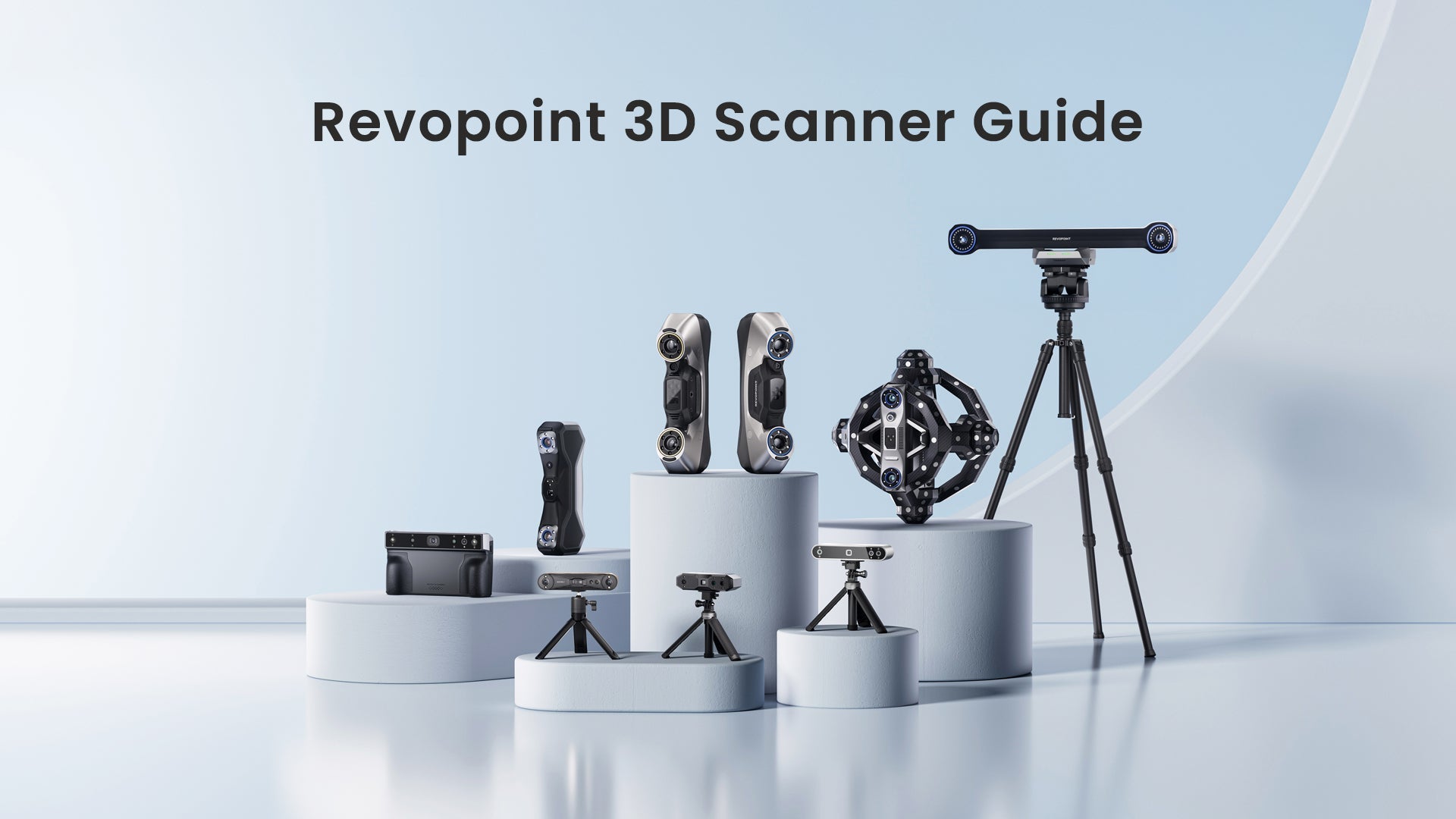
3D scanners like the Revopoint MetroY series and Trackit make it more accessible than ever to capture dense, accurate geometry for quality control and reverse-engineering workflows. However, raw scan data alone doesn’t tell you whether a part meets design requirements. This is where GD&T comes in: it provides a clear framework for interpreting scanned geometry and evaluating functional tolerances.

Some GD&T callouts, such as flatness, parallelism, and surface profile, are well-suited to scan data because scanners capture overall shapes with high resolution. Other features, especially very tight tolerances or small holes, may still require traditional metrology tools for precise verification. Understanding GD&T helps users know which features can be reliably checked with a scan and when supplemental measurement methods are necessary.
Why GD&T Matters
Learning to use GD&T tools like those in Revo Measure enables clearer communication, more reliable designs, and fewer manufacturing errors. It helps designers specify what truly matters, assists machinists in understanding what needs to be held tightly, and guides inspectors in measuring parts as intended.
Most importantly, it creates a shared language among everyone involved in making a product, removing ambiguity, lowering costs, and ensuring parts from different suppliers still fit together perfectly.
Leave a comment
This site is protected by hCaptcha and the hCaptcha Privacy Policy and Terms of Service apply.