When prototype work starts falling behind, the problem is often not the cutting time. It is the time lost before machining begins: measuring existing parts, rebuilding geometry in CAD, fixing unclear surfaces, and checking whether the digital model truly matches the physical object. Combining 3D scanning with CNC milling helps reduce that delay by turning real-world geometry into usable manufacturing data earlier in the process.
For fast prototyping, this matters most when teams are working with existing components, hand-shaped models, complex curves, worn parts, or designs that need quick revision. Instead of rebuilding everything manually, they can capture the geometry, refine what matters, and move into CNC machining with less guesswork. The result is not just speed for its own sake, but a more efficient path from concept, sample, or reference part to a machine-ready prototype.
Why 3D scanning improves CNC prototyping workflows
Traditional prototype development can be slow when geometry is difficult to model from scratch. A team may need to measure an object by hand, rebuild surfaces in CAD, generate toolpaths, machine the first version, inspect it, then repeat the process again. That approach still works for simple parts, but it becomes less efficient when shapes are organic, asymmetrical, feature-rich, or tied to an old physical part without usable design files.
3D scanning improves that workflow by capturing the actual shape directly. Instead of spending hours recreating each contour, users can work from scan data, clean it up, align it, and prepare it for CAD or CAM use. This is especially helpful in reverse engineering, replacement part development, fixture design, ergonomic product development, and iterative prototype refinement.
The biggest advantage is that scanning reduces interpretation. The workflow starts from what the part really is, not what someone estimates from manual measurements. That helps preserve subtle details and lowers the chance of geometry drift before machining even begins.
Where 3D scanning fits in the scan-to-mill process
A practical scan-to-mill workflow usually includes the following steps:
- scan the object, model, or part
- clean the data and remove unwanted noise
- align the scan to the right coordinate system or CAD reference
- convert the mesh into a format suitable for design or machining
- import it into CAD or CAM software
- set stock, orientation, and machining strategy
- generate toolpaths for roughing and finishing
- machine the prototype
- optionally rescan the finished part for comparison or validation
This structure supports both direct replication and controlled redesign. In some cases, the goal is to copy an existing part. In others, the scan is only the starting point, and the geometry is adjusted before machining to improve fit, thickness, mounting features, or overall performance.
When scanning is more useful than redrawing
Not every prototype project needs a scanner. For simple mechanical parts with complete drawings and clean dimensions, manual CAD is often still the fastest route. But scanning becomes more useful when the part includes geometry that is difficult to recreate efficiently.
That often includes:
- freeform or organic surfaces
- handmade mockups or sculpted samples
- worn or legacy components
- deep grooves, recessed areas, or complex edges
- parts that must match an existing assembly
- shapes with subtle asymmetry or ergonomic contouring
In these cases, scanning helps teams start with a more realistic digital foundation and spend their time on engineering decisions rather than unnecessary reconstruction.
How this workflow saves time in fast prototyping
The speed benefit comes from compressing multiple steps across the development cycle. Scanning can reduce geometry capture time, lower manual CAD effort, and improve revision control from one prototype to the next.
A first version can be scanned, machined, tested, rescanned, and adjusted more efficiently because the digital and physical forms stay connected throughout the process. If a fit issue appears after machining, the next revision does not need to begin from scratch. The team can compare what changed, identify where it changed, and respond more accurately.
This is especially important in product development environments where the first prototype is only one step in a larger iteration cycle. The real value is often not just the first part, but how much faster the second and third versions can be produced.

Accuracy considerations in a scan-to-CNC workflow
Speed is only useful if the captured geometry is reliable enough for engineering use. In CNC prototyping, scan data can influence toolpaths, surface decisions, fit checks, fixture design, and CAD reconstruction. That makes scan quality an important part of the process.
Useful performance factors include:
- volumetric accuracy
- single-frame accuracy
- ability to capture edges and fine details
- performance on dark or shiny surfaces
- handling of holes, crevices, and recessed features
- export compatibility for CAD, CAM, and inspection software
If the scan is too noisy, incomplete, or visually good but dimensionally weak, the downstream machining result may suffer. That is why prototype teams working on engineering-grade tasks often prefer industrial or metrology-oriented scanning systems rather than tools aimed mainly at casual modeling.
Common uses of 3D scanning with CNC milling
This workflow supports a range of prototype and manufacturing tasks:
Reverse engineering
Scan an existing part, rebuild only the necessary features, and machine a replacement or updated version.
Prototype refinement
Capture a first physical sample, modify it digitally, and machine a second version with more control.
Ergonomic product development
Scan hand-shaped grips, handles, wearable surfaces, or sculpted forms and turn them into machinable models.
Fixture and tooling creation
Use scan data to create soft jaws, locating nests, checking fixtures, and custom supports that match a part accurately.
Machined part validation
After milling, rescan the part to compare it to nominal geometry and support the next revision.
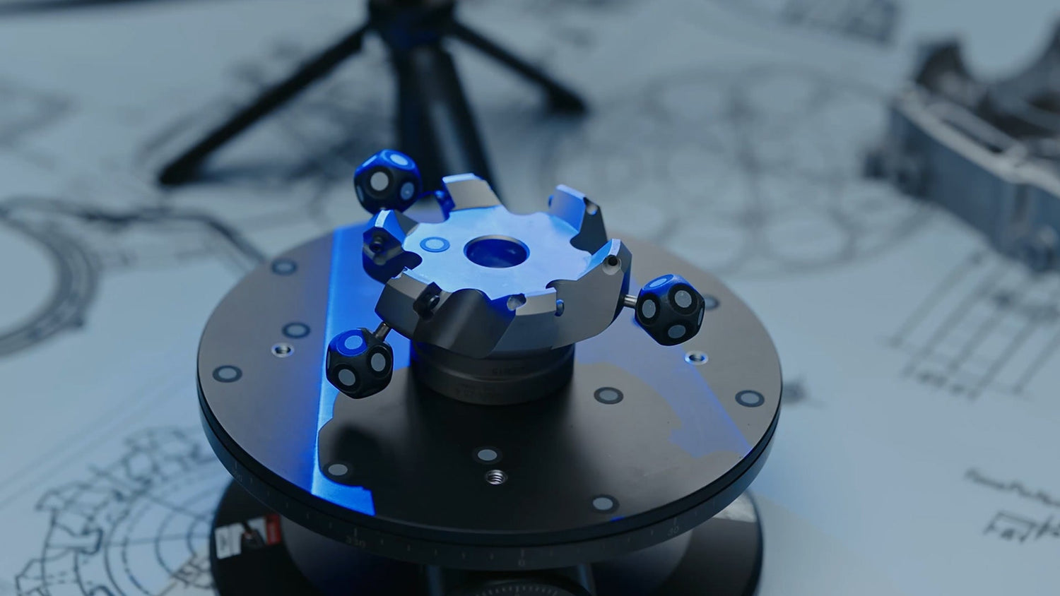
Revopoint MetroY Ultra for small to medium CNC prototyping
For fast prototyping involving small to medium workpieces, Revopoint MetroY Ultra fits this workflow well because it is built around practical geometry capture rather than display-only scanning. It combines multi-line blue laser scanning with full-field structured light, giving users more flexibility when parts vary in shape, detail level, and surface condition.
MetroY Ultra includes five scanning modes: 34 crossed laser lines for fast capture, 15 parallel lines for finer details, a single laser line for deep holes and recessed areas, structured light for feature-rich marker-free scans, and Auto Turntable Mode for repeatable desktop scanning. In prototype work, that matters because one project may involve broad surface capture, while the next may require attention to edges, grooves, or harder-to-reach features.
"Its volumetric accuracy is 0.015 mm + 0.04 mm × L(m), with single-frame accuracy up to 0.015 mm. It also supports up to 3,000,000 points per second in laser scanning and up to 7,000,000 points per second in structured light mode. For reverse engineering, scan-to-CAD preparation, prototype measurement, and machining workflows, that combination helps keep scanning efficient without sacrificing data quality. It also supports Wi-Fi 6 and common output formats, making it easier to move captured data into downstream design and manufacturing work."
Revopoint Trackit for larger prototype and industrial scanning workflows
When prototype work extends into larger parts, assemblies, or industrial components that are less convenient to reposition, Revopoint Trackit becomes more relevant. Trackit is an optical tracking 3D scanner designed for marker-free scans, combining a high-accuracy scanner with a tracker unit to support small-to-large object capture.

For CNC-related prototyping, its main value is workflow efficiency on bigger workpieces. Instead of placing large numbers of markers or repeatedly resetting the part, users can perform marker-free laser scans while the tracking system monitors the scanner’s location in real time. That makes it easier to capture larger shapes for redesign, machining preparation, inspection, or fixture planning.
"Trackit supports 30 blue cross-line lasers for efficient surface capture and a single blue laser line for narrow features such as holes, grooves, and recessed areas. It offers volumetric accuracy of 0.02 mm + 0.04 mm × L(m), a recommended part size range from 0.01 to 6 m, and standalone handheld scanning for hidden areas that may not be visible to the base station. For larger prototype parts or industrial components where setup time and repositioning can slow everything down, that makes Trackit a strong fit for scan-to-mill and scan-to-measure workflows."
FAQ
What is the main benefit of combining 3D scanning with CNC milling for fast prototyping?
It reduces the time between physical geometry capture and machining. That helps teams move faster from an existing part or sample into CAD, CAM, and CNC production.
Is 3D scanning always better than manual CAD modeling?
No. For simple, fully dimensioned parts, manual CAD can still be more efficient. Scanning is more useful when geometry is complex, irregular, worn, or difficult to measure.
Can scan data be used directly for machining?
Sometimes yes, but not always. Mesh data can often go into CAM software, but some parts still need cleanup, alignment, or scan-to-CAD work before machining.
What kinds of prototype projects benefit most from this workflow?
Reverse engineering, ergonomic product development, handmade model digitization, fixture design, and prototype revision cycles are some of the most common examples.
Conclusion
Combining 3D scanning with CNC milling for fast prototyping gives teams a more direct way to move from real-world geometry to machined parts. It reduces unnecessary rebuilding work, supports faster iterations, and improves the connection between physical samples, digital models, and CNC output.
For smaller and medium-sized prototype work, Revopoint MetroY Ultra offers a strong balance of speed, flexible scan modes, and engineering-focused accuracy. For larger industrial parts and marker-free workflows, Revopoint Trackit supports a more scalable approach. In the right workflow, both help make prototyping more efficient without turning scanning into an extra layer of complexity.

Leave a comment
This site is protected by hCaptcha and the hCaptcha Privacy Policy and Terms of Service apply.